
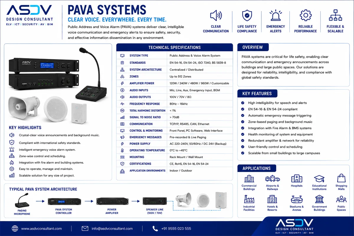
A single centralized amplifier rack, however well built, represents a single point of failure: if that rack fails during an emergency, the entire building's voice evacuation capability fails with it. Networked amplifier architecture distributes amplification capacity across multiple physical units connected via the PAVA network, so that failure of any individual amplifier affects only its own limited zone capacity — and N+1 redundancy design ensures a spare amplifier automatically takes over even that.
This distributed, redundant approach mirrors resilience principles long established in data center and telecommunications infrastructure — no single component failure should be capable of causing complete system failure — applied to the specific context of life-safety voice evacuation, where the cost of an undetected single point of failure is measured in human lives, not just downtime.
Amplifier Redundancy Architecture Comparison
| Architecture | Failure Impact | Redundancy Level | Typical Application |
|---|---|---|---|
| Single Centralized Amplifier | Total system loss on failure | None | Legacy/non-compliant small systems |
| N+1 Centralized Redundancy | No loss, spare takes over | 1 spare amplifier per group | Mid-size buildings, single-rack rooms |
| Distributed Networked N+1 | Zone-limited, auto-failover | Spare capacity across network | Campus/multi-building, high-rise |
| Fully Distributed Zone Amplifiers | Single zone only, isolated fault | Per-zone or per-floor redundancy | Airports, metros, large malls |
Technical Design: Networked Amplifier Redundancy Architecture
- Automatic failover switching: Networked amplifier controllers continuously monitor the health of every amplifier in the system; on detected failure, load is automatically redirected to the designated spare unit within the certified failover time (typically under 1 second for EN 54-16 compliant systems)
- Load distribution planning: Amplifier capacity is sized and distributed across the building such that the loss of any single unit (or its designated backup) does not exceed the remaining system's total available power capacity for the affected zones
- Power supply redundancy: Each amplifier is typically paired with redundant, independently monitored power supplies (mains plus battery backup per EN 54-4), ensuring amplifier failure and power failure are treated as separate, independently mitigated fault modes
- Distributed rack placement: Rather than centralizing all amplification in a single equipment room, networked architecture allows amplifier racks to be physically distributed across a campus or high-rise building, limiting the blast radius of any single rack-level incident (fire, flood, physical damage)
- Real-time fault reporting: Amplifier health, failover events, and remaining redundancy capacity are reported in real time to the fire command center and, where cloud-monitored, to a centralized facilities dashboard, ensuring maintenance teams are alerted before redundancy margin is exhausted
- Capacity planning for growth: Networked amplifier systems are designed with headroom for future zone expansion, avoiding the need to re-architect redundancy calculations each time the building's PAVA coverage grows
Predictive Amplifier Health Analytics
Networked amplifier systems will increasingly incorporate predictive failure analytics — using continuous performance telemetry (thermal trends, output distortion, power draw patterns) to identify amplifiers showing early signs of degradation and proactively schedule replacement before a failure occurs during an actual emergency, shifting redundancy strategy from purely reactive failover to genuinely predictive maintenance across an entire building portfolio.